Conservation of Angular Momentum - Rotational Kinematics
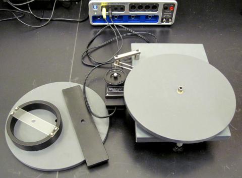
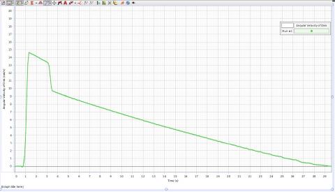
A solid disk is slipped over a (fairly) frictionless rotating vertical spindle. A rotary motion sensor is lightly held against the rim of this disk to measure the disk’s angular velocity. This bottom disk is given a spin and then other objects are carefully dropped on top of it. Capstone is used to graph the angular velocity of the rotating system before, during, and after the collision takes place. Straight-line fits are used to find the initial angular velocity of the bottom and then the final angular velocity of the total system after the collision.
Browse to the Conservation of Angular Momentum template and double-click: K:\Physics\Demonstrations\Conservation of Angular Momentum
- Click on <Record>
- Give the disk a clockwise spin
- Drop the ring on the center spindle
- Click on <Stop>
- Use the Hand and the Scale double-headed arrow to shift and scale the graph to magnify the region of interest.
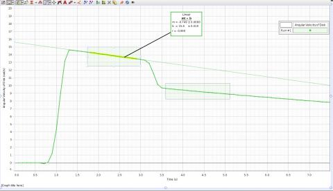
- Click on the Highlight Range Tool and draw a box around the initial angular velocity portion of the graph.
- Click on the Curve Fitting Tool down arrow and select “Linear”.
- Click on the Curve Fitting tool button to draw the best straight line through the selected data.
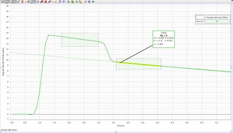
- Again, click on the Curve Fitting Tool and draw a box around the final angular velocity portion of the graph.
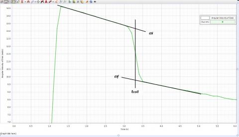
- Find the mid-point of the collision time tcoll and read the angular velocities wi and wf from the Angular Velocity scale for this time – the line intersections.
Angular Momentum L
Li = IDisk1 wi
Lf = (IDisk1 + IRing) wf
More Information