Fourier Synthesis
The Fourier synthesizer generates a fundamental sinusoidal signal of 440 Hz (concert A) and eight harmonics:
Fundamental 440 Hz
2nd harmonic 880 Hz (2 X 440)
3rd harmonic 1320 Hz (3 x 440)
4th harmonic 1760 Hz (4 X 440)
5th harmonic 2200 Hz (5 X 440)
6th harmonic 2640 Hz (6 X 440)
7th harmonic 3080 Hz (7 X 440)
8th harmonic 3520 Hz (8 X 440)
9th harmonic 3960 Hz (9 X 440)
Each harmonic has a separate output jack for connection to an oscilloscope, as well as separate phase and amplitude controls. The phase controls consist of 90° and 180° switches and a -90° to +90° knob. When all of the controls are set to zero, the individual output jacks produce (minus) cosine waves.
The fundamentals and all harmonics can be switched into a summing amplifier, where they are added and sent to a high impedance BNC jack for display on an oscilloscope and to an audio amplifier and speaker with a separate volume control for listening. The summing amplifier introduces its own phase shift of 180°, so that positive cosine is produced at the output of the summing amplifier as opposed to the individual minus cosines at the input. This is important when synthesis of complex (e.g., a square) waveform is attempted.
To correctly observe the phase relationships between fundamentals and harmonics, the external trigger on the oscilloscope must be connected to the trigger output of the synthesizer. If any of the signals appear out-of-phase with the rest, pushing the reset button will bring it in-phase.
For the synthesis of square waves, only odd harmonics are required. The relative amplitudes and phases of these off harmonics are:
For cosines: 1 -1/3 (-0.33) 1/5 (0.20) -1/7 (-0.14) 1/9 (0.11) etc.
For sines: 1 1/3 (0.33) 1/5 (0.20) 1/7 (0.14) 1/9 (0.11) etc.
These amplitudes must be set by oscilloscope measurement of the amplitude of each harmonic (not by the crude scales on the synthesizer knobs). the output of the harmonics may be displayed one-by-one on Channel B of a the Pasco 850 Interface through the use of the individual output jacks. The output of the summing amplifier may also be displayed. Note that the summing amplifier introduces a phase shift of 180° from the displays of the the individual harmonics. In addition, Channel A of the 850 interface must be connected to the trigger output of the synthesizer so that the changes in phase may be observed.
- Turn on the power to the Fourier synthesizer.
- Press the RESET button on the synthesizer to initialize all of the internal oscillators to be in phase.
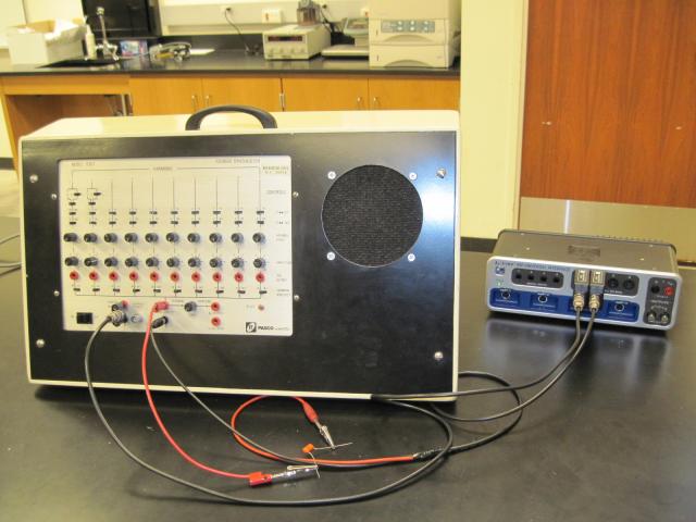
- Connect the trigger cable from the TRIGGER OUTPUT of the synthesizer (GND tab to the black banana jack) to ANALOG CHANNEL A BNC adapter.
- Connect the black banana plug of the other BNC lead to the 10K Output Ground banana jack. Connect the red banana plug to the second Harmonic 1 OUTPUT banana jack. Use a 0.01 uf capacitor in the red lead to block unwanted DC voltages produced by the synthesizer. Connect the other end of the cable to the ANALOG CHANNEL B BNC adapter.
- Open "Fourier Synthesizer.cap"
Now set up the synthesizer:
- Set all of the synthesizer 0°«90° and 0°«180° phase switches to 0°.Set all of the VARIABLE PHASE knobs to their center (0) positions.
- Set all of the AMPLITUDE knobs fully counterclockwise (0).
- Set all of the SUMMING AMPLIFIER switches to OUT.
- Switch on the SUMMING AMPLIFIER switch for the fundamental frequency (1)—the second left-most switch. The first fundamental, also labeled 1, first on the left, will not be used.
- Click on Monitor
- Increase the AMPLITUDE knob for the first harmonic (the second from the left) to about the 3 o'clock position. Set the Set the 0°«180° phase switch to 180°. Adjust the VARIABLE PHASE so that the cosine wave starts at the top of a crest.
- Move the red banana lead to the 3rd harmonic jack. Set the AMPLITUDE to 1/3 the amplitude of the fundamental. Adjust the VARIABLE PHASE so that the –cosine wave starts at the bottom of a trough.
- Switch in the 3rd harmonic to the SUMMING AMPLIFIER. You can fine tune the VARIABLE PHASE to achieve a symmetric summed waveform.
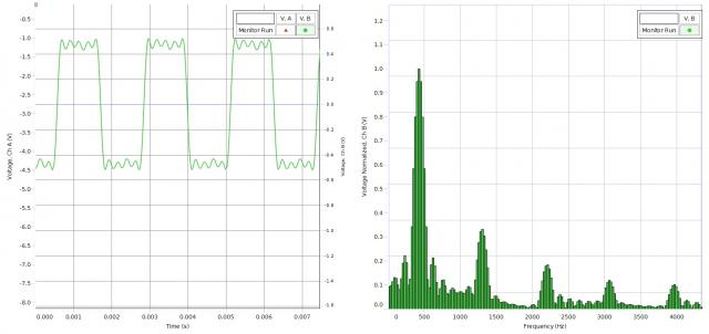
- In turn, add in the 5th, 7th, and 9th harmonics.
Turn up the speaker volume so that you can hear your synthesized square wave. While listening to the speaker, change the various phase knobs and switches. What changes do you see in the summed output? What changes do you hear?
NOTES:
- If the waveform will not trigger properly, try reopening the Capstone file.
- Each time the Capstone file is opened, the sampling rate may need to be reset to 50 kHz and the FFT bins increased to the maximum.